Hello,
I don't understand why reinforcement look different.
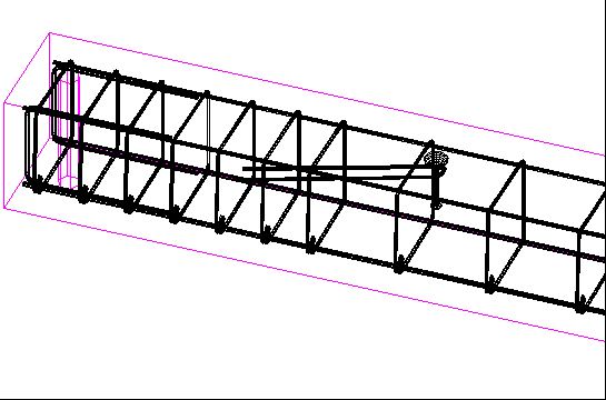
That how it looks in model:

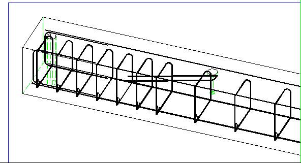
But when i'm trying create view, it looks:

Why it looks different? How to create view correctly?
Thank you.
Im Allplan Connect Forum tauschen sich Anwender aus, geben wertvolle Tipps oder beraten sich bei ganz konkreten Aufgabenstellungen − auch international.
Und damit wirklich keine Frage unbeantwortet bleibt, unterstützen die Mitarbeiter des Technischen Supports ebenfalls aktiv das Forum.
Melden Sie sich jetzt an und diskutieren Sie mit!
Hello,
I don't understand why reinforcement look different.
That how it looks in model:

But when i'm trying create view, it looks:

Why it looks different? How to create view correctly?
Thank you.
Hi,
I think the rebars modeled by "copy and move" in the isometric view instead of "placing it" but maybe I'm wrong
To create a view, I use Associative View in Create - Engineering View - Associative View then Create View. First, Your model should be in a plan view (Top View). Afterward, you can choose in which direction you want to see the model (for side, front/rear view).
But If you want a Isometric view. First, your model should be in isometric view then Create View choose Free for "input option" then left click, back to plan view (top view).. done.
D.W.Wicaksono
Thank you for your answer.
About views i'm understood.
And about modeling rebars, for example I have ifc file with columns. First I'm making top view and side view of any column, than using Engineering - Bar Shape place rebars in views. Some times i'm using "copy and move". Or it isn't correct?
I am sorry. I think you're right with the modelling rebars not always placing the bars sometimes I copy or even mirror it. But It's kind a strange view. Mine also even worse. Bars are not rounded.
D.W.Wicaksono
Hi i_trofimov,
I just see this message, i'm not sure if you find your answer.
If you compare the model/animation and the associative view, you will never sse the same result.
Because the display in the animation and isometric view from the model use the 3D graphic card to display the real bars.
When you create an associative view, we want to get a result!
So the bars are converted automatically like:
- line
- double line
- fills
The setting is defined Inside the tool/option of engineering part.
Let's say a bars in 3D is like an Octogan with few facets. So in face, you can see a lot of line. When we work on plane we just want to see a nice line.
Bye & Good Use!
Mr Judy GURAVADU
Responsable Technique Préfabrication & Ingénierie
Precast Sales & Support
Allplan France & Allplan Precast
Since 2006